Why Power Supply Architecture Matters in Modern Electronics
Key Takeaways:
- The topologies universities emphasize are NOT what industry uses the most
- Knowing which power supply is inside a product matters more than theory
- Simple decision rules get you 80% of the way there
- Download reference designs, don't start from scratch
Power supplies are everywhere, powering everything from your gaming computer and laptop right down to your cell phone or electric toothbrush. But the real unsung hero is the little circuit right after the grid-the power switching converter, or power electronics.
These specialized circuits manage high currents and operate within tight, high-energy delivery windows that can easily cause harm if not handled correctly. Yet, most engineers don't really know how they work. In many electronics classes, power converters are often just a specialized or optional elective, which means they are not commonly understood. The disconnect between academic theory and industry needs creates a gap in knowledge, even among professionals designing printed circuit boards.
It's true that many engineers are intimidated by the world of power electronics. No worries, though. In this article, we will demystify power electronics by exploring the most important types of power converters, how they affect your devices, and how to choose the right one for your application. But first, let's address the root of the problem: why are these essential circuits covered so little in academia, and why is there such a disconnect between the classical topologies we study and what real companies are actually seeking?
The Disconnect Between Academia and Industry in Power Supply Design
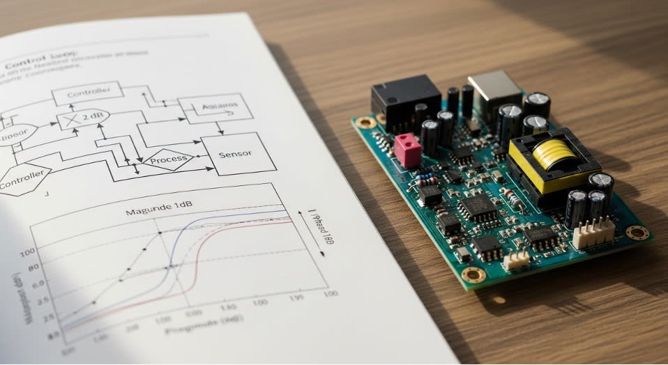
Figure 1: Academic setting vs. Industry PCB
In 2019, Apple wanted to interview me for their power electronics team.
Apple was my dream company. I knew one day when I got the chance to interview with them, I'd knock it out of the park.
The internal recruiter said: "You need to know flyback converters really well. That's what we use."
Flyback? That topology we spent two weeks on in grad school while spending months on buck-boost analysis and control theory? I kind of remembered it.
Fast forward a week later and do the interview.
I bombed that interview.
I knew power electronics. I've been researching DC-DC converters since 2009. I could derive transfer functions in my sleep. But I didn't know the one topology Apple actually cared about.
That's when it hit me: Industry doesn't care about the topologies you spent the most time learning. They care about what needs to go inside their products.
What Power Supply Topologies are Inside Your Everyday Devices?

Figure 2: Modern Consumer Electronics
Here's what nobody teaches you in school. That is, which power supply topology you can find in the following devices:
|
Devices |
Power Supply Topology |
|
Your toaster |
None. It's a resistive heating element plugged straight into AC. Sometimes the simplest answer is the right one. |
|
Your MacBook charger |
The Flyback converter. Every USB-C power adapter, every phone charger, every wall wart under 100W? Flyback. It's THE workhorse for isolated AC-DC supplies. Apple's power team obsesses over this one topology. |
|
Your desktop PC power supply |
Modern ATX supplies use LLC resonant converters for the main 12V rail (replaced the old forward/half-bridge designs) plus a flyback for the 5V standby rail that's always on. |
|
Your smartphone |
A Power Management IC (PMIC) with multiple buck converters stepping down battery voltage to different rails (CPU, GPU, memory), LDOs for sensitive analog circuits, and boost converters for LED backlight and camera flash. A typical smartphone PMIC manages 5-12 voltage rails in a single chip. |
|
Your car's infotainment system |
Synchronous buck converters everywhere. The "12V" automotive battery actually swings from 2V (cold-crank) to 42V (load-dump transients), so these bucks need a wide input range to step down to 5V, 3.3V, 1.8V for all the electronics. |
|
NVIDIA Jetson or AI boards |
Complex power trees with cascaded architectures: main supply → intermediate voltage → multiple point-of-load buck converters. Separate rails for VDD_CORE, VDD_CPU, VDD_GPU, VDD_CV, all with dynamic voltage scaling. |
See the pattern? Real products use specific topologies for specific reasons. Not the topologies textbooks emphasize and jeopardize our GPAs for, during Fall and Spring semester.
Luckily, through failed interviews and alternatively, professional role success, I can write down the things they should have put in the text book…which topologies are in use, why and how to pick them.
In the next section, I'll share a decision framework that lets you choose the right power supply architecture instead of guessing which one will work.
A Simple Decision Framework for Choosing Power Supply Topologies
Here's a shortcut to determine the right topology for your application. We'll go based on power consumption (Watts). If your circuit demands a certain overall Wattage, that narrows down choices significantly.
Power Level < 5W, No Isolation Needed:
- LDO if voltage drop is small (<2V) and you don't care about efficiency
- Buck converter if efficiency matters or voltage drop is large
Power Level 5-100W, Isolation Required:
- Flyback. Period. This is what every wall adapter uses. Don't reinvent this.
Power Level 100-200W, Isolation Required:
- Forward converter or LLC resonant
- Check manufacturer reference designs
Power Level > 200W, Isolation Required:
- LLC resonant, half-bridge, or full-bridge
- Get a power supply specialist involved
Multiple Voltage Rails in Portable Device:
- Use a PMIC. Don't design discrete converters. The integration is worth it.
Automotive or Wide Input Range:
- Buck-boost if input can go above AND below output voltage
- Wide-range buck if input is always higher
That's it. That's the decision tree.
Picking the Right Architecture is Not Enough: Common Power Supply Design Mistakes and How to Avoid Them.
While selecting the correct architecture is the big task, it's equally as important that the power supply functions correctly. Even the best topology will fail if these common errors are present, wasting the effort in design and the architecture selection you went through in the first place. Let's examine the two most frequent mistakes applicable to every design.
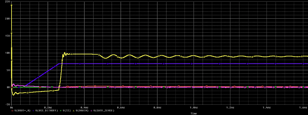
Figure 3: PSPICE Simulation of output voltage with overshoot and ringing (yellow)
Mistake #1: No Ground Plane
"I'll save routing space by using ground traces instead of a plane."
Then you spend weeks debugging noise issues, EMI problems, and mysterious resets.
Use a solid ground plane. One continuous ground on the bottom layer. Connect it to your power supply return at ONE point. Don't route traces across gaps in the ground plane.
This isn't optional for modern designs. Even 2-layer boards need a ground plane.
Mistake #2: Not Adding Margin to Current Calculations
You calculated 500mA, so you grabbed a 500mA supply. Then your board randomly resets.
The problem? You calculated average current, not peak. You didn't account for inrush when capacitors charge at startup. You didn't add margin for real-world conditions.
The fix: Multiply your calculated current by 1.5 to 2x. Always.
If you think you need 500mA, design for 750mA-1A. Datasheets give typical conditions at 25°C. Real boards don't operate in typical conditions.
Now that you know what mistakes to avoid, regardless of the power supply architecture you choose, you're ready to power on the design.
How to Start Your Power Supply Design the Right Way
If you have 15 minutes:
Go to Texas Instruments, Analog Devices, or STMicroelectronics. Search for a reference design that matches your power requirements. Download it.
Don't start from scratch. The hard work-component selection, PCB layout, compensation networks-is already done. Adapt it to your needs.
If you have an hour:
Use a circuit simulation tool like PSpice. Load the reference design. Run a simulation with YOUR input voltage range and load conditions.
Simulate worst-case: minimum input voltage + maximum load + highest temperature. If it works in simulation, you're 80% of the way there.
If you're starting a new design:
- Calculate power budget (sum all loads, multiply by 1.5-2x)
- List voltage rails needed
- Use the decision framework above to pick topology
- Find manufacturer reference design
- Adapt reference design to your requirements
- Simulate worst-case
- Build prototype
Don't skip steps 4 and 6. Reference designs save weeks. Simulation catches problems before hardware.
The Real Lesson
You don't need to be a power electronics expert. You need to:
- Know which topologies are actually used in production
- Start with proven reference designs
- Add proper margin to your calculations
- Use a ground plane
- Simulate before you build
Everything else is details.
The next time you're staring at Digi-Key with a thousand power supply options, remember: you're not choosing components. You're choosing architecture.
Pick the one that's proven in millions of products. Adapt the reference design. Test it thoroughly.
That's how power supplies get designed in industry. Not from first principles. From proven patterns.
Now you know the patterns.
Quick Reference Guide: Power Supply Topologies by Application
|
Application |
Topology |
Why |
|
Wall adapter <100W |
Flyback |
Simple, isolated, cost-effective |
|
Desktop PC main rail |
LLC Resonant |
High efficiency at high power |
|
Desktop PC standby |
Flyback |
Always-on, low power |
|
Smartphone power |
PMIC (integrated) |
Multiple rails, small footprint |
|
Automotive ECU |
Synchronous Buck |
Wide input range, efficient |
|
Battery-powered IoT |
Buck or PMIC |
Efficiency critical |
|
High-current (>10A) |
Multiphase Buck |
Distributed heat, lower ripple |
Resources:
- Power Electronics Handbook (comprehensive reference)
- Texas Instruments (TI) Power Supply Design Seminars
- Cadence PSpice
- Manufacturer application notes (Some are better than textbooks for practical applications, but be careful to verify the designs. They may contain mistakes)
The gap between university and industry isn't circuit complexity. It's knowing which tools to actually use.