How Many Microvias Can You Safely Stack? A Deep Dive Into HDI Reliability Physics
As HDI designs push toward ever-finer pitches and higher layer counts, stacked microvias have become indispensable for escaping dense BGAs and achieving the routing density modern applications demand. But stacking microvias isn't without risk. The question isn't whether you can stack three, four, or even five microvias, it's whether your design will survive thermal cycling, reflow, and years of field operation without developing latent interconnect failures.
This post examines the physics that govern microvia stack reliability, helping you make informed decisions about when stacking is appropriate and when staggering offers a more robust solution.
Stacked vs. Staggered: The Fundamental Trade-off
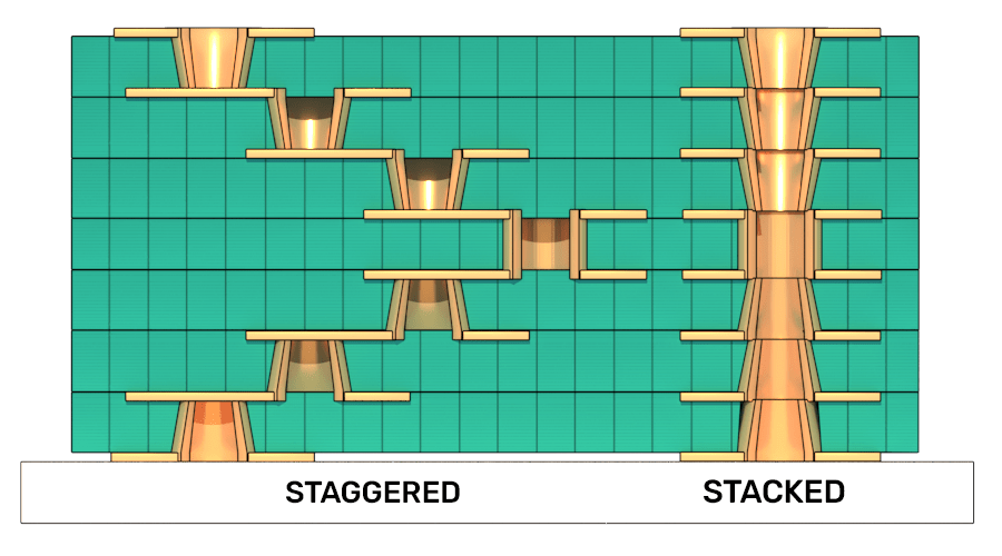
Figure 1: Staggered microvias vs. Stacked microvias (credit: Cadence)
The choice between stacked and staggered microvias represents a fundamental trade-off between routing density and manufacturing complexity. Stacked microvias place each successive via directly on top of the previous one, creating a vertical column of interconnects. This approach maximizes routing density, which iscritical when breaking out fine-pitch BGAs at 0.4mm or below, but requires that each underlying microvia be filled and planarized before the next layer is built.
Staggered microvias, by contrast, offset each successive via from the one below. This eliminates the need for copper filling between lamination cycles, reducing process steps and cost. The trade-off is reduced routing density: the offset distance consumes valuable real estate beneath dense components.
From a reliability standpoint, however, the distinction runs deeper than process complexity.
The Physics of Stress Distribution
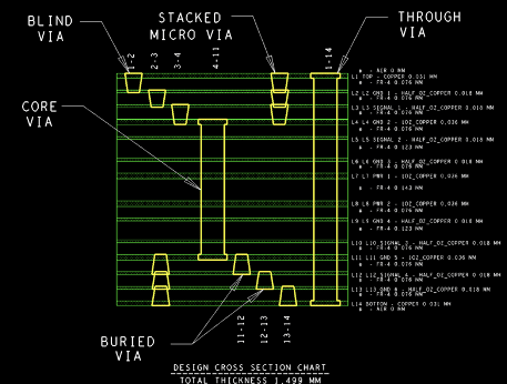
Figure 2: 3-level stack showing interface design (credit: John Burkhert)
When a PCB undergoes thermal excursion, whether during reflow assembly or operational cycling—the copper and dielectric materials expand at different rates. Copper has a coefficient of thermal expansion (CTE) around 17 ppm/°C, while FR-4 dielectrics exhibit z-axis CTEs ranging from 40 to 70 ppm/°C depending on resin content and glass weave. This CTE mismatch generates stress at every copper-dielectric interface.
In a stacked microvia column, these stresses accumulate vertically. Each via-to-via interface becomes a potential failure point, and the cumulative strain across multiple stacked vias can exceed what the copper microstructure can accommodate. The result is fatigue cracking, whichtypically initiates at the weakest interface and propagates until electrical continuity is lost.
Staggered configurations distribute this stress differently. Because each via terminates on a capture pad rather than directly on another via's fill material, the stress concentration at any single point is reduced. The offset geometry also allows the dielectric material to absorb and distribute strain across a larger volume.
When Stack Height Becomes Reliability-Critical
Industry experience and IPC reliability studies suggest that two-level stacked microvias (connecting three layers) generally perform reliably across most applications and thermal profiles. Three-level stacks (four layers) enter a gray zone where material selection, via geometry, and expected thermal exposure all influence survivability.
Beyond three levels, reliability becomes increasingly design-specific. Four and five-level stacks have been successfully deployed in high-reliability applications, but they demand careful attention to:
- Via diameter and aspect ratio: Larger diameter microvias (6 mil vs. 4 mil) provide more copper cross-section to resist fatigue.
- Fill quality: Voiding in copper fill creates stress concentrations that initiate cracking.
- Dielectric thickness: Thinner dielectrics (sub-3-mil) experience higher strain rates during thermal cycling.
- Thermal profile severity: Lead-free reflow temperatures (~260°C peak) stress stacked structures more severely than leaded profiles.
A critical but often overlooked factor is whether the stack terminates on a buried mechanical via. Stacking microvias directly on top of a mechanically drilled buried via creates a particularly vulnerable structure. The mechanical via's larger geometry and different fill characteristics create an interface prone to cracking. When possible, offset microvias from buried mechanical vias, then stack from that offset point.
How Material Choice Changes Survivability
Material selection dramatically influences stacked microvia reliability. The key parameters are z-axis CTE, glass transition temperature (Tg), and decomposition temperature (Td).
Standard FR-4 materials like Isola 370HR or NanYa NP-175 work well for two-level stacks in moderate thermal environments. Their z-axis CTE behavior is well-characterized, and fabricators have extensive experience optimizing fill processes for these materials.
For three-level or deeper stacks, materials with lower z-axis CTE and higher thermal stability become important. Low-CTE laminates reduce the strain differential that drives fatigue, while higher Tg materials maintain mechanical integrity through lead-free reflow temperatures. Materials like Megtron 6, Isola I-Speed, and Panasonic Megtron 7 offer improved thermal performance, though at higher cost.
Resin content also matters. Higher resin content materials flow more readily during lamination, improving fill quality and reducing voiding. However, higher resin content typically correlates with higher z-axis CTE. This trade-off requires careful balancing based on your specific stack configuration and reliability requirements.
For sequential lamination HDI, ensure your chosen material system is rated for multiple lamination cycles. Some high-speed materials that perform excellently in conventional builds may not survive the repeated thermal exposure of three or four lamination cycles without degradation.
Table 1. CTE & Material Property Comparison: FR-4 vs. High-Speed Materials
|
Material Property |
Standard FR-4 |
High-Tg FR-4 (e.g., Isola 370HR) |
Isola I-Speed |
Panasonic Megtron 6 (R-5775) |
|
Material Class |
General Purpose |
Enhanced Epoxy |
High Speed / Low Loss |
Ultra-Low Loss |
|
CTE Z-Axis (Pre-Tg) |
50–70 ppm/°C |
45–50 ppm/°C |
45 ppm/°C |
45 ppm/°C |
|
CTE Z-Axis (Post-Tg) |
250–300 ppm/°C |
220–250 ppm/°C |
230 ppm/°C |
260 ppm/°C |
|
CTE Z-Axis Expansion (50°C to 260°C) |
3.5% – 4.0% |
2.8% – 3.2% |
2.5% – 2.7% |
< 2.5% |
|
CTE X/Y-Axis |
14–18 ppm/°C |
13–17 ppm/°C |
16 ppm/°C |
14–16 ppm/°C |
|
Tg (Glass Transition) |
130°C – 140°C |
180°C |
180°C (DSC) |
185°C (DSC) |
|
Td (Decomposition) |
310°C |
340°C |
360°C |
410°C |
|
Dk (Dielectric Constant) @ 10 GHz |
~4.2 – 4.5 |
~4.0 |
3.63 |
3.71 |
|
Df (Dissipation Factor) @ 10 GHz |
0.015 – 0.020 |
0.020 |
0.0060 |
0.0040 |
|
Cost Factor |
1x (Base) |
1.5x – 2x |
2x – 3x |
3x – 4x |
- Standard FR-4: Based on Isola DE104 (Generic 135°C Tg epoxy system).
- High-Tg FR-4: Based on Isola 370HR (180°C Tg).
- Isola I-Speed: Official Isola I-Speed Datasheet (IPC-4101/102).
- Panasonic Megtron 6: Official Panasonic R-5775 Datasheet.
- Note: Dk and Df values vary slightly based on specific glass weave construction (e.g., 1080 vs.
Practical Guidelines
Given these physics, consider the following guidelines when planning microvia stacking:
- Two-level stacks: Generally safe across standard materials and thermal profiles. Use freely where routing density demands.
- Three-level stacks: Require attention to material selection and via geometry. Validate with your fabricator and consider thermal cycling qualification if the application demands high reliability.
- Four+ level stacks: Treat as high-risk structures requiring explicit reliability validation. Work closely with fabrication engineering to optimize fill quality and consider hybrid approaches (stagger where possible, stack only where necessary).
- Stacking on mechanical vias: Avoid when possible. If unavoidable, offset the first microvia from the first microvia from the mechanical via, then stack from that point.
The most reliable HDI designs achieve a balance by stacking where density is essential and staggering where space permits, using material selection and process control to maximize survivability at the critical interfaces.