Advanced PSpice Features for Circuit Analysis with OrCAD X
Key Takeaways
-
Identify critical components with Sensitivity Analysis to focus your tolerance budgets where they matter most.
-
Predict yield and performance variability with Monte Carlo simulations tailored to real-world manufacturing conditions.
-
Automatically tune and validate designs using the Optimizer and Smoke Analysis to meet performance goals and ensure reliability.
PSpice allows for complete circuit simulation and verification
While transient, DC, and AC sweep analyses are fundamental for verifying basic circuit functionality, modern electronic designs often require deeper insights into performance variations, reliability margins, and manufacturing yields. OrCAD X offers a suite of advanced PSpice features for circuit analysis that address these complex needs. These tools move beyond simple "Does it work?" questions to answer "How well will it work given real-world component variations?", "Which components are most critical to performance?", and "How can this design be optimally tuned?". This article introduces key advanced PSpice features—Sensitivity Analysis, Monte Carlo Analysis, Optimizer, and Smoke Analysis—explaining the design challenges they solve and then detailing how to leverage them within OrCAD X.
Advanced PSpice Features for Circuit Analysis Overview
|
Advanced PSpice Feature |
Addressed Design Challenge |
Main Purpose |
|
Identifying which components or parameters have the most significant impact on critical circuit performance metrics. |
|
|
|
Predicting how components' manufacturing tolerances will affect a design's overall performance distribution and yield. |
|
|
|
Finding the best component values to meet multiple, often conflicting, design specifications efficiently. |
|
|
|
Ensuring individual components operate within their safe electrical and thermal limits to prevent premature failure. |
|
How to Perform Sensitivity Analysis in OrCAD X
The first advanced PSpice feature for circuit analysis we want to discuss is sensitivity analysis, which identifies which component parameters are most critical to your circuit's measurement goals.
Assign Component Tolerances
Before running the analysis, ensure the components in your design have tolerances assigned. This can be done via PSpice > Advanced Analysis > Assign Tolerances.
You can set global tolerances for component types (e.g., all resistors ±5%) or apply instance-specific tolerances to individual parts, overriding global settings. Tolerances can also be applied to parameters within subcircuit models (e.g., a diode's breakdown voltage).
Define Key Performance Measurements
-
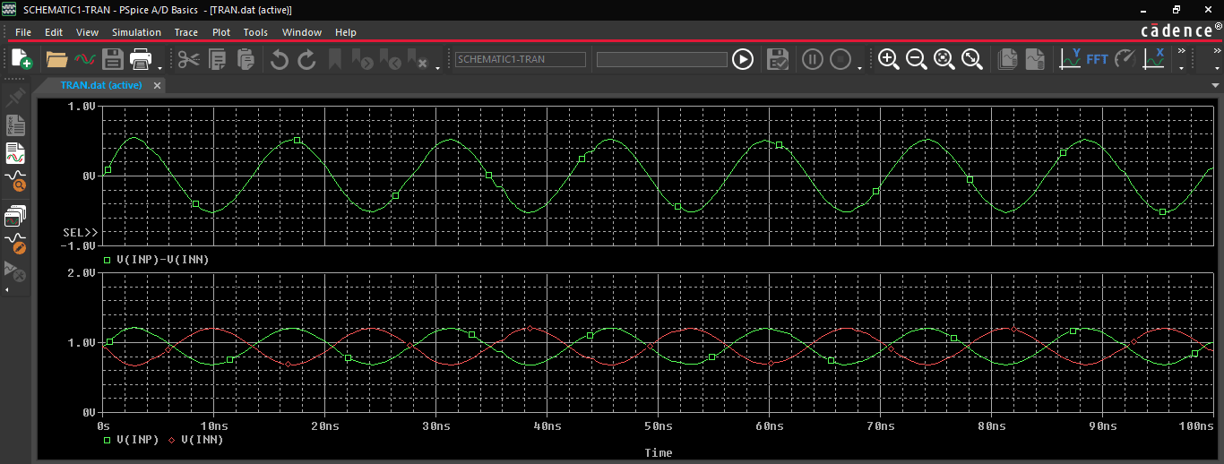
Run a standard PSpice simulation (e.g., AC Sweep for a filter, Transient for timing).
-
In the PSpice waveform viewer (Probe window), use Trace > Evaluate Measurement to define and calculate the specific performance metrics you are interested in. These become the goals for the sensitivity analysis.
Launch and Configure Sensitivity Analysis
-
Return to OrCAD X Capture and select PSpice > Advanced Analysis > Sensitivity.
-
In the Sensitivity analysis window, click to import the measurements you created in the PSpice waveform viewer.
-
The parameters table will display all device properties that have tolerances applied. Ensure "Sensitivity" is selected as the analysis type in the top left.
Run and Interpret Results
Click the "Start" icon to run the analysis. The results will show the original (nominal) value for each measurement and the min/max range expected when components vary by their tolerances.
Crucially, the "Sensitivity Component Filter" lists components and their relative sensitivity – the percentage change in your measurement for a 1% change in that component's parameter. Components with high relative sensitivity values are the most critical to your measurement goal.
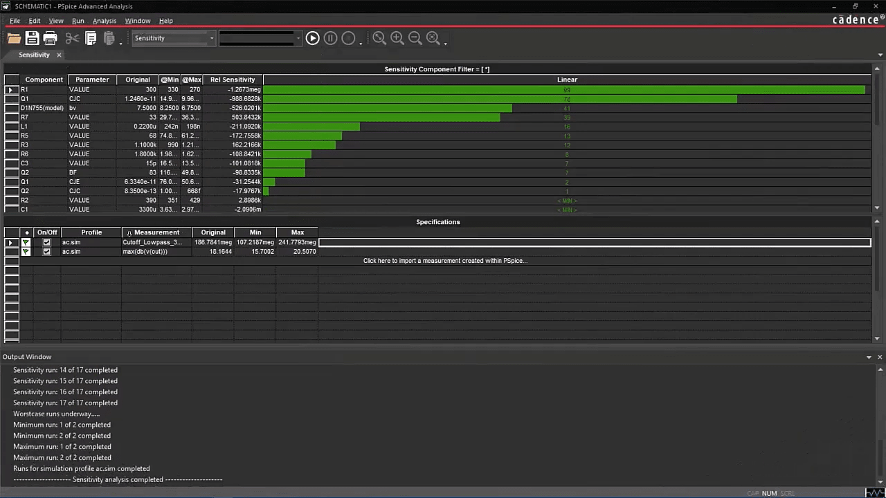
Sensitivity Component Filter showing the relative sensitivity of circuit components
How to Perform Monte Carlo PSpice Analysis in OrCAD X
Monte Carlo analysis is one of many advanced PSpice features for circuit analysis. It predicts the statistical yield of your circuit meeting specific performance targets given component tolerances.
Assign Tolerances and Distributions
Assign tolerances using PSpice > Advanced Analysis > Assign Tolerances.
For each tolerated parameter, you can also specify its statistical distribution (e.g., uniform, Gaussian). Global distributions are often set in the PSpice initialization file, while instance-specific ones are properties on the schematic.
Define Performance Measurements
Run a standard PSpice simulation and use Trace > Evaluate Measurement in the waveform viewer to define the performance metrics you need to assess for yield (e.g., minimum acceptable gain, maximum acceptable rise time).
Launch and Configure Monte Carlo Analysis
-
In Capture, select PSpice > Advanced Analysis > Monte Carlo.
-
Import the measurements from your standard PSpice run into the statistical information spreadsheet.
-
Click Edit > Profile Settings to configure the Monte Carlo run. Key settings include:
-
Number of Runs: Typically 100s or 1000s for good statistical significance.
-
Random Number Seed: This can be fixed for repeatable results or varied.
Run and Interpret Results
Click "Start" to begin the multiple simulation runs. The results are displayed as:
-
Probability Density Function (PDF) / Histogram: Shows the distribution of a measurement across all runs. You can see how many runs fall into specific performance bins.
-
Cumulative Distribution Function (CDF): Shows the cumulative probability. By placing markers on the CDF graph (e.g., at your minimum acceptable bandwidth), you can directly read the yield – the percentage of runs that met or exceeded that specification.
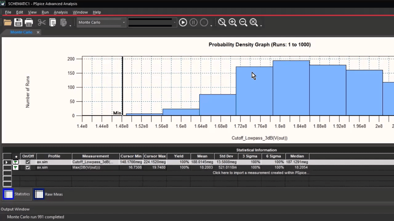
Monte Carlo Simulation for the cutoff frequency of a low-pass filter
How to Use the PSpice Optimizer Analysis in OrCAD X
The PSpice Optimizer is also an advanced PSpice feature for circuit analysis and helps automatically tune component values to meet defined performance specifications.
Identify Optimizable Parameters
Decide which component values in your circuit you want the Optimizer to adjust (e.g., values of specific resistors and capacitors).
Define Performance Goals (Measurements)
Run a standard PSpice simulation and define the critical performance metrics you want to achieve using Trace > Evaluate Measurement (e.g., target a 3dB cutoff frequency, maximize gain, minimize settling time).
Launch and Configure Optimizer
-
In Capture, select PSpice > Advanced Analysis > Optimizer.
-
In the "Parameters" spreadsheet, click to select and add the component parameters you identified in step 1. For each parameter, you can set the current value and define a minimum/maximum range within which the Optimizer can vary it.
-
Import your defined measurements into the "Specification" spreadsheet. For each measurement, specify your goal (e.g., Goal = Minimum, Value = 195MHz for bandwidth; Goal = Minimum, Value = 32dB for gain).
-
Under Edit > Profile Settings, select an optimization engine (e.g., "Modified LSQ" for initial optimization, then potentially "Discrete" for rounding to standard values) and set parameters like the maximum number of optimization runs.
Run and Analyze Optimized Values
-
Click "Start" to run the optimization. The tool will iteratively adjust the chosen component parameters and re-simulate to converge on your goals.
-
The "Parameters" worksheet will display the "Optimized Value" for each component. Note that the initial optimized values might be non-standard.
-
(Optional) Re-run with the "Discrete" engine, providing a list of standard component values (e.g., 5% resistor values) to find the closest commercially available parts that still meet the goals.
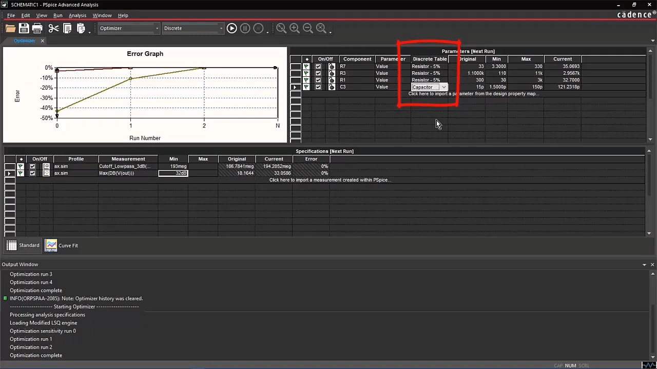
PSpice Optimizer Discrete engine finding the best component values
How to Use Smoke Analysis in OrCAD X
Smoke analysis in PSpice helps ensure the reliability of your design by checking if individual components are operating within their safe electrical and thermal limits.
Ensure Accurate Component Models
The accuracy of Smoke Analysis heavily relies on the quality of the PSpice models used. Models should ideally contain information about their Safe Operating Area (SOA) limits (maximum voltage, current, power dissipation, temperature). PSpice's extensive library, which includes models from major component vendors, often contains this data. For custom parts, you may need to ensure these limits are correctly defined or available.
Define Derating Factors (Optional but Recommended)
For increased design robustness, it's good practice to operate components well below their absolute maximum ratings. PSpice allows you to apply derating factors.
Access derating settings via PSpice > Edit Simulation Profile > Options > Smoke. Here, you can set global derating percentages for various parameters (e.g., derate maximum power by 20%, meaning a warning will trigger if a component exceeds 80% of its rated power). You can often apply specific derating files for more granular control.
Run a Relevant Simulation
Smoke analysis is typically performed based on the results of a primary simulation type that stresses the circuit appropriately, such as:
-
DC Operating Point Analysis: To check steady-state stress.
-
Transient Analysis: To check stress under dynamic conditions, peak currents, and voltages over time.
-
DC Sweep: To check stress across a range of input voltages or operating conditions.
Ensure the simulation profile for one of these analyses is set up to cover the worst-case or typical operating conditions you want to evaluate.
Enable and Configure Smoke Analysis
-
In the Simulation Settings dialog for your chosen profile (e.g., Transient), navigate to the "Data Collection" tab (or a similar section related to waveform saving).
-
Ensure that data relevant to Smoke analysis is being saved. Usually, enabling "Save all" for voltages and currents is sufficient, or you can specify that device currents and power dissipations are marked for saving if a more selective data collection is desired.
-
Go to the PSpice > Edit Simulation Profile > Options > Smoke tab and enable Smoke analysis.
-
Review and adjust derating factors if not already set globally.
-
You may also want to specify which parameters to check (e.g., Max Current, Max Voltage, Max Power Dissipation, or Junction Temperature if thermal models are used).
Run the Simulation
Execute the primary simulation (e.g., PSpice > Run). PSpice will perform the underlying analysis (DC, Transient, etc.) and then conduct the Smoke analysis based on those results.
Interpret Smoke Analysis Results
After the simulation, a Smoke Report will be generated. This report lists components that have violated their SOA limits (or the derated limits). The report will indicate:
-
The component reference designator.
-
The parameter that was violated (e.g., "Max Power Dissipation").
-
The simulated value that caused the violation.
-
The limit (or derated limit) that was exceeded.
You can click on entries in the report to cross-probe back to the schematic or view relevant waveforms around the time/condition of the violation. Address any flagged violations by either selecting a more robust component, adjusting circuit parameters to reduce stress, or improving thermal management if temperature is the issue.
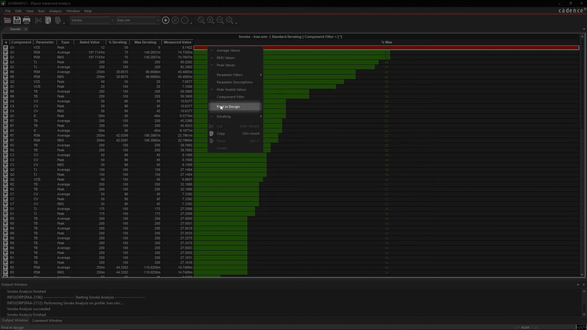
Locate the component with reliability issue with Smoke Analysis
Mastering advanced PSpice features for circuit analysis means making smarter, more reliable design decisions. With OrCAD X, engineers can explore performance sensitivities, predict yield with statistical accuracy, tune circuit behavior automatically, and validate component reliability under stress. Don’t settle for "works on paper," get real-world ready instead. Start your free trial of OrCAD X or explore the full OrCAD X platform to unlock the power of advanced circuit simulation.
Leading electronics providers rely on Cadence products to optimize power, space, and energy needs for a wide variety of market applications. To learn more about our innovative solutions, subscribe to our newsletter or our YouTube channel.