How to Create a New PSpice Model or Library
Key Takeaways
-
OrCAD X provides two main methods for creating new PSpice models: the wizard-based Modeling Application for quick parameter entry and the PSpice Model Editor for detailed, datasheet curve-based creation.
-
The Modeling Application in OrCAD X Capture allows users to generate PSpice models (like MOSFETs or diodes) by directly inputting key electrical parameters from component datasheets.
-
The PSpice Model Editor enables more precise model creation by inputting data points from characteristic curves (e.g., diode I-V curves) and then extracting SPICE parameters.
Accurate simulation in PSpice relies heavily on having the correct simulation models for the components in your design. While PSpice comes with an extensive default library, there are many instances where you'll need to create new models for specific parts or import models obtained from third-party vendors. Understanding how to create a new PSpice model or library is crucial for performing realistic circuit simulations. This guide explores two main methods to create a new PSpice model: the built-in Modeling Application or the PSpice Model Editor for datasheet-based creation.
How to Create a New PSpice Model Summary
|
Method |
Description |
Typical Use Case |
Key Steps |
|
PSpice Modeling Application |
Wizard-based approach within OrCAD X Capture for creating models by entering datasheet parameters. |
Creating models for common devices like MOSFETs, diodes, and sources quickly. |
Place > PSpice Part > Modeling Application, Enter Parameters, Place Model. |
|
PSpice Model Editor |
Standalone tool to create models by inputting data points from the datasheet characteristic curves. |
Detailed, accurate model creation for diodes, BJTs, etc., when curves are available. |
Launch Model Editor, File > New > Model, Enter curve data, Tools > Extract Parameters, Save .lib file. |
How to Create a New PSpice Model or Library Using the Modeling Application
For common device types like MOSFETs, diodes, or various voltage/ current input sources used in simulations, OrCAD X Capture offers a wizard-like tool called the Modeling Application. This wizard provides a guided approach to creating custom PSpice models based on key datasheet parameters without needing to edit SPICE netlist syntax directly. In this example, we will create a P-channel MOSFET.
Step 1: Open the Modeling Application
Within OrCAD X, select Place > PSpice Part > Modeling Application from the menu.
Step 2: Select Device Type
A panel will open, allowing you to choose the type of model to create (e.g., Power MOSFET, Diode, Passives, Sources, etc.). For a P-channel MOSFET, we select "Power MOSFET" and then choose "P-Channel MOSFET."
Step 3: Enter Datasheet Parameters
The application will present a series of fields corresponding to key electrical characteristics. These values can be modified and obtained from the component datasheet.
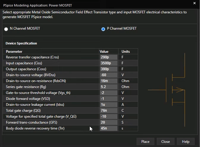
PSpice Modeling Parameters for P Channel MOSFET
Step 4: Place the Component
After entering all known parameters, click the "Place" button. The Modeling Application will generate the PSpice model and an associated schematic symbol. You can then click on your schematic to place the newly created component. Use keyboard shortcuts like 'V' to flip vertically or 'H' to flip horizontally if needed. Models created this way are immediately ready for simulation within the current design.
Creating a PSpice Model from Datasheet Curves using PSpice Model Editor
While the Modeling Application is excellent for quick model generation based on discrete parameters, sometimes a more detailed approach is needed, especially when you have characteristic curves from a component datasheet. For these scenarios, understanding how to create a new PSpice model or library using the standalone PSpice Model Editor provides greater control and accuracy. This method lets you define device behavior by entering data points from the component’s curves. In this example, we will create a diode model.
Step 1: Launch the PSpice Model Editor
Open the PSpice Model Editor application (usually found in your Cadence program group). When prompted, select "Capture" as the default design entry tool if you intend to use the models there.
Step 2: Create a New Model
-
Go to File > New.
-
In the "Model" tab, select "New Model".
-
Name your model (e.g., "UF180_Diode").
-
Ensure "Use Device Characteristic Curves" is selected.
-
Choose the correct "Model Type" (e.g., "Diode"). Click "OK".
Step 3: Enter Data from Datasheet Curves
The editor will present tabs corresponding to different device characteristics.
-
Forward Current: Enter V_forward and I_forward data points directly from the diode's IV curve on its datasheet. As you enter data, the plot in the Model Editor will update.
-
Junction Capacitance: Enter junction capacitance values at different reverse voltage points based on the datasheet graph.
-
Reverse Leakage: Input reverse leakage current and voltage values.
-
Reverse Breakdown: Enter parameters like VZ (Zener voltage, if applicable).
-
Reverse Recovery: Enter parameters like Trr (Reverse Recovery Time). Some of this data may need to be obtained from the component vendor if it isn’t explicitly provided in the datasheet.
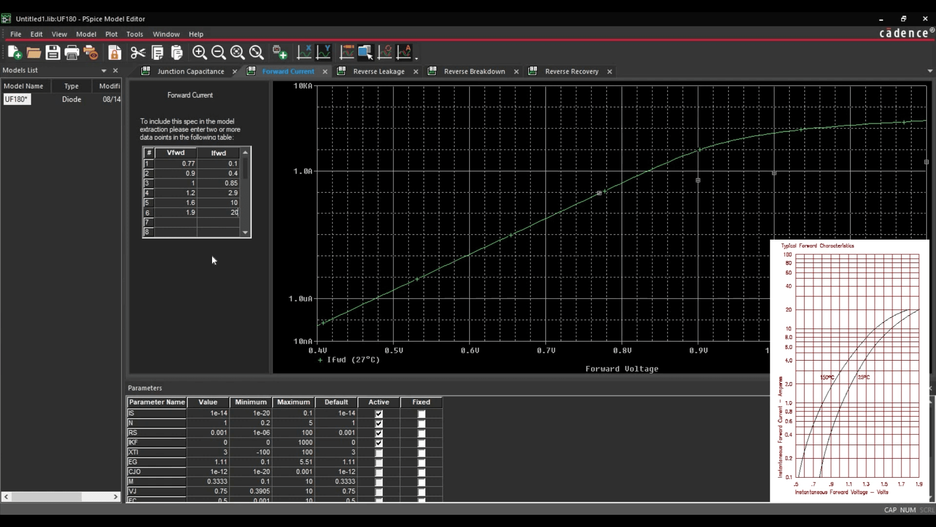
Change Forward Current Curve Values Based on the Manufacturer’s Datasheet
Step 4: Extract Parameters
Once you have entered all of the available datasheet information, go to Tools > Extract Parameters. The Model Editor will calculate the underlying SPICE model parameters based on the data you provided.
Step 5: Save the Model
-
Select File > Save As.
-
Create a new folder if desired.
-
Enter a file name (e.g., "MyDiodes.lib"). PSpice model files typically use the .lib extension. Click "Save". This .lib file now contains the SPICE netlist definition for your new model.
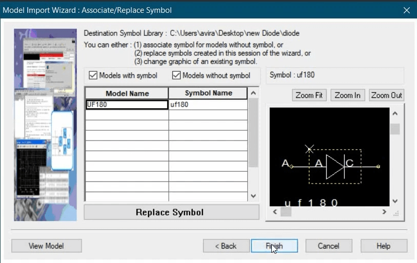
Step 6: Creating a Symbol for the Model
After creating the .lib file, you will need a schematic symbol for it:
-
Re-open PSpice Model Editor (or use the same session).
-
Go to File > Model Import Wizard.
-
In the Input Model Library field, browse to the .lib file that you just saved. The Destination Symbol Library field will typically auto-populate to save the symbol library in the same location.
-
Click Next. The Model Editor will attempt to assign a default symbol based on the model type (e.g., a standard diode symbol for a diode model). You can use this or click "Replace Symbol" to choose/create a custom one.
-
Click Finish. A summary log will appear. A schematic symbol file linked to your model will be created.
This new symbol library is added to your OrCAD X Capture library path, and the component can be placed and simulated.
Knowing how to create a new PSpice model or library significantly expands your simulation capabilities within OrCAD X. Whether you use the quick wizard-based Modeling Application for common devices, delve into the PSpice Model Editor for datasheet-driven model creation, these methods allow you to simulate a much wider range of components accurately.
Ready to build your custom simulation library? Try OrCAD X free trial, including PSpice, or explore the full OrCAD X platform to leverage its comprehensive design and simulation environment.