RLC Circuit Analysis Guide with PSpice in OrCAD X
Key Takeaways
-
Running a simulation in PSpice first requires enabling a simulation profile and using specific PSpice components (R, L, C, Sources, Ground) for analysis.
-
Simulation Profiles (e.g., Transient for time-domain, AC Sweep for frequency-domain) define the type and parameters of the RLC circuit analysis to be performed.
-
The PSpice waveform viewer allows detailed analysis of results by plotting voltages/currents and using cursors for precise measurements of waveforms.
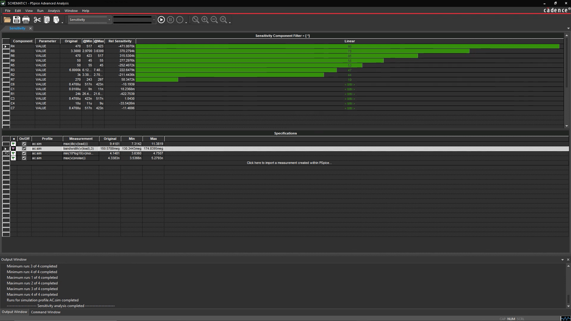
PSpice Sensitivity Analysis
Understanding how basic circuits like resistor-inductor-capacitor (RLC) networks behave is fundamental to electronics design. While manual calculations work for simple cases, analyzing complex interactions, transient responses, and frequency characteristics requires simulation. Cadence PSpice, integrated within the OrCAD X environment, provides a powerful virtual simulation platform for this purpose. This guide offers a practical introduction to performing RLC circuit analysis using PSpice, enabling you to verify and refine your designs before physical prototyping.
Introduction to RLC Circuit
Resistor-inductor-capacitor (RLC) circuits are fundamental to understanding electrical systems. Each component performs a unique function, as listed below::
-
Dissipate energy (Resistors)
-
Store energy in magnetic fields (Inductors)
-
Store energy in electric fields (Capacitors)
They are essential building blocks in numerous electronic systems. The unique characteristics of RLC circuits stem directly from this interplay between energy dissipation and storage. This interaction leads to defining behaviors such as resonance, frequency-dependent filtering, and distinct transient responses often involving oscillations and damping. Understanding and analyzing these responses is crucial for successfully designing oscillators, filters, tuning circuits, and many other applications.
RLC Circuit Analysis Workflow with PSpice
|
Step |
Action |
Guide |
|
1. Project Setup |
Create a new OrCAD X Capture project, ensuring the PSpice simulation capability is enabled. |
File > New > Project (Check "Enable PSpice Simulation") |
|
2. Circuit Building |
Place PSpice-specific components (R, L, C, sources, ground) onto the schematic canvas and define their values/ parameters. |
Place > PSpice Component > Ground, Diode, RLC, Sources |
|
3. Wiring |
Connect the placed components using the wire tool to form the desired RLC circuit topology. |
Place > Wire or Toolbar Icon |
|
4. Profile Configuration |
Define the type of analysis (e.g., Transient, AC Sweep) and its parameters (run time, frequency range) via a simulation profile. |
PSpice > New Simulation Profile |
|
5. Simulation Run |
Execute the PSpice simulation based on the active profile settings. |
PSpice > Run or Toolbar Icon |
|
6. Results Analysis |
View and interpret the generated waveforms (voltage, current vs. time/frequency) in the PSpice waveform viewer (Probe window). |
PSpice Waveform Viewer (opens automatically) |
Detailed Guide for RLC Circuit Analysis with PSpice
Let's look at each step in more detail on how to perform RLC circuit analysis in PSpice.
Step 1 & 2: Project Setup and Building Your RLC Circuit
In an OrCAD X Schematic, first, create a new project via File > New > Project, name it appropriately, and critically, check the "Enable PSpice Simulation" box. This activates the PSpice menus and toolbar.
Next, build your RLC circuit using PSpice-compatible parts found under the Place > PSpice Component menu. You can also search for your part with the Search function.
-
Passives: Select Resistor, Capacitor, and Inductor and place them. Double-click components to set values.
-
Ground: Place the essential PSpice ground reference (0) using Place > PSpice Component > PSpice Ground.
-
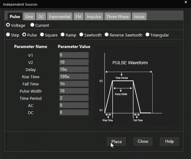
Sources: Choose appropriate sources (e.g., VDC, VAC, VPULSE) or use Place > PSpice Component > Modeling Applications for customized source (independent or PWL). Configure source parameters.
Step 3: Wiring the Components
Use the 'Wire' tool (Place > Wire) to connect the components according to your RLC circuit design. Ensure all nodes are correctly connected and save the schematic.
Step 4: Configuring the Simulation Profile
Define the analysis parameters in a Simulation Profile (PSpice > New Simulation Profile). Name the profile (e.g., "RLC_Transient") and configure the settings.
Common PSpice Analysis Type
|
Analysis |
Purpose |
Key Settings |
Typical Application |
|
Time Domain (Transient) |
Simulates circuit behavior over time. |
Run to time, Start/End times, Step ceiling. |
Step/Pulse response, oscillations, damping. |
|
AC Sweep/Noise |
Simulates frequency response (gain/phase). Requires AC source. |
Start/End Frequency, Points/Decade, Sweep Type. |
Filter characteristics, resonance frequency. |
|
DC Sweep |
Sweeps a DC source and calculates DC operating points. |
Source Name, Start/End Values, Increment. |
IV curves (less common for pure RLC). |
|
Bias Point |
Calculates initial DC operating point (voltages/currents). |
(Often run implicitly). |
Initial conditions for capacitors/inductors. |
|
Sensitivity, Monte Carlo, Smoke, Optimization |
Analyze statistical variations, stress, and tune performance. |
Various statistical/stress/goal-based parameters. |
Yield prediction, reliability checks, design tuning. |
For analyzing basic RLC behavior, focus on Time Domain (Transient) for time-based responses or AC Sweep/Noise for frequency characteristics. Set the relevant parameters like run time or frequency range.
Steps 5 & 6: Running the Simulation and Analyzing Results
You can select voltage or current markers (PSpice > Markers) on key nodes. Then, run the simulation (PSpice > Run).
The PSpice waveform viewer will open:
-
View Waveforms: Observe voltage/current plots. Pre-placed markers usually display automatically.
-
Add Traces: Use Trace > Add Trace to plot other signals or mathematical functions.
-
Measure with Cursors: Activate cursors (Trace > Cursor > Display) for precise measurements (time, voltage, frequency, phase) directly on waveforms.
Lastly, you can go back to the schematic, add different markers, change your components, or set up a different simulation profile and rerun the simulation.
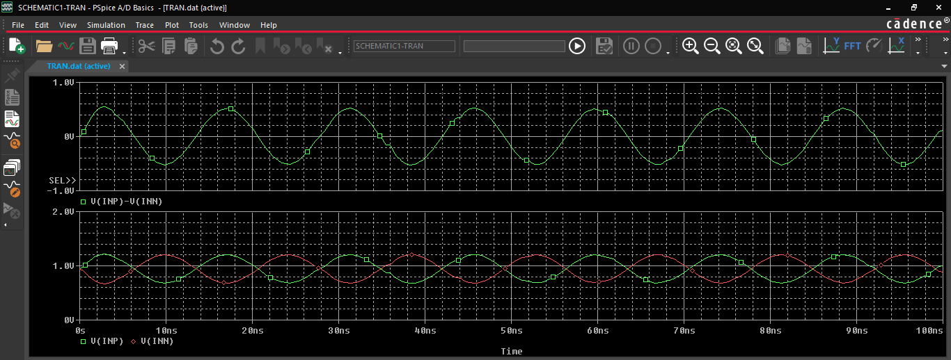
PSpice allows for complete circuit simulation and verification
Beyond Basic RLC Analysis: Advanced PSpice Capabilities
Leveraging powerful integrated analog and mixed-signal simulation engines alongside an extensive model library, PSpice enables engineers to simulate, verify, and refine designs ranging from simple circuits to complex systems. While mastering fundamental analyses like Transient and AC Sweep (essential for basic RLC circuits) is key, PSpice extends far beyond these basics, offering advanced capabilities for deeper insight, optimization, and reliability assessment.
-
Sensitivity Analysis: Identifies which component parameters most significantly impact circuit performance, helping optimize tolerances versus cost.
-
Monte Carlo Analysis: Predicts circuit behavior across statistical variations in component values, assessing manufacturing yield and robustness.
-
Smoke Analysis: Checks if components are operating within their safe voltage, current, power, or temperature limits, preventing electrical overstress and improving reliability (critical in automotive).
-
Optimizer: Automatically tunes component values to meet specific performance goals defined by the designer.
-
MATLAB/Simulink Integration: Enables co-simulation of electrical circuits with mechanical, hydraulic, or thermal systems for comprehensive electro-mechanical analysis (valuable for IoT and complex systems).
These advanced features, combined with the extensive model library, make PSpice a powerful tool for demanding applications in industries like automotive (ECU simulation, reliability), IoT (sensor/communication device testing), and power electronics (switching regulators, magnetic design).
Performing basic RLC circuit analysis using PSpice within OrCAD X provides insight into your circuit’s operation. This virtual analysis capability is fundamental to modern electronic design and opens the door to leveraging advanced PSpice features for tackling more complex design challenges and ensuring performance, reliability, and manufacturability. Explore further with OrCAD X for free, which includes PSpice Standard access, or explore the full OrCAD X platform to discover its comprehensive simulation capabilities.